
Impeller Casting Process: How 3D-Printed Sand Molds Improve Pump Components
Tabla de contenido
- The impeller casting process converts a hydraulic design into a metal component capable of transferring energy to a liquid or gas.
- Blade geometry, flow passages, wall thickness, alloy selection, gating, solidification, machining, and balancing all influence the final performance.
- Investment casting is often selected for smaller, complex impellers requiring detailed surfaces, while resin sand casting is suitable for larger components and lower-volume production.
- 3D-printed sand molds and cores can shorten the pattern-development stage and support complex internal geometries.
- A printed mold does not replace foundry engineering; pouring behavior, gas generation, shrinkage, feeding, and solidification must still be controlled.
- CNC machining establishes accurate bores, shaft interfaces, sealing faces, and reference surfaces after casting.
- Dimensional inspection, material verification, non-destructive testing, and dynamic balancing should be matched to the operating risk.
- The best manufacturing route depends on impeller size, alloy, blade complexity, quantity, surface requirements, and service environment.
What Is the Impeller Casting Process?
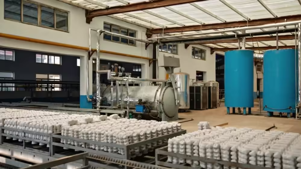
The impeller casting process is a manufacturing route in which molten metal is poured into a prepared mold to form the blades, hub, shrouds, and flow passages of an impeller. After solidification, the casting is cleaned, heat-treated when necessary, machined, inspected, and balanced before installation.
Un impulso is a rotating component that transfers energy between a machine and a fluid. It is commonly used in centrifugal pumps, compressors, turbines, mixers, and other fluid-handling equipment.
For pump applications, manufacturing quality directly affects how smoothly the liquid enters, passes through, and leaves the rotating component. Small deviations in blade profile, passage width, concentricity, or balance can contribute to turbulence, vibration, noise, reduced efficiency, or premature wear.
Impeller Geometry
Impeller geometry includes blade number, blade angle, inlet eye diameter, outlet diameter, hub dimensions, passage width, and shroud arrangement. These features determine how the component interacts with the operating fluid.
The casting method must reproduce this geometry without creating inaccessible cavities, thin incomplete sections, or excessive dimensional variation.
Hydraulic Surface
The hydraulic surface is the area that comes into direct contact with the moving liquid or gas. Surface irregularities can disturb flow, especially around blade edges and narrow passages.
The required surface condition depends on rotational speed, fluid properties, pump duty, and efficiency expectations. Some areas may be improved through blasting, polishing, grinding, or controlled machining.
Casting Allowance
A casting allowance is additional material intentionally added to surfaces that will be machined later. It gives the manufacturer enough stock to remove casting variation and create accurate final dimensions.
Too little allowance can leave unclean surfaces, while excessive allowance increases machining time and may introduce additional distortion or material waste.
Why Impellers Are Difficult to Cast
Impellers are more demanding than simple solid castings because they combine curved blades, changing wall sections, central hubs, narrow flow channels, and strict rotational requirements.
An impeller may look symmetrical in a CAD model, but the molten metal does not necessarily fill and cool symmetrically. The impeller casting process must account for fluid flow, heat transfer, shrinkage, gas release, mold strength, and metal cleanliness.
Curved and Narrow Blades
Thin blades cool faster than a heavy hub. If molten metal reaches them too slowly or at an unsuitable temperature, incomplete filling or cold shuts may occur.
Increasing the pouring temperature is not automatically the correct solution. Higher temperatures can also increase oxidation, gas reactions, mold interaction, or solidification time.
Uneven Section Thickness
The hub and shrouds may contain more metal than the blade edges. These different section sizes cool at different rates and can create shrinkage, residual stress, or distortion.
Smooth thickness transitions and an appropriate feeding system help control these risks. Simulation may also be used to study filling and solidification before mold production.
Enclosed Flow Passages
Closed impellers contain passages between two shrouds. These internal spaces require cores or carefully designed mold sections.
Complex passages may be difficult to produce with conventional core boxes. This is one reason 3D-printed sand cores have become relevant to modern impeller casting.
Rotational Balance
Uneven mass distribution creates centrifugal forces when the impeller rotates. Even if the component meets basic dimensional requirements, imbalance can increase bearing loads and vibration.
The casting, machining, and balancing stages must therefore be planned as one connected manufacturing process.
Main Impeller Casting Methods
The correct method depends on component size, geometry, alloy, quantity, tolerance, surface requirements, and expected post-processing.
| Casting method | Main strengths | Main limitations | Suitable impeller applications |
|---|---|---|---|
| Silica sol investment casting | Detailed blades, smooth surfaces, good dimensional consistency | More process stages and size limitations | Small and medium precision impellers |
| Resin sand casting | Flexible size range and suitable for complex, heavy components | Rougher surface and wider as-cast tolerances | Large pump, turbine, and industrial impellers |
| Conventional sand casting | Flexible materials and practical tooling | More pattern and core preparation | General industrial impellers |
| 3D-printed sand mold casting | Patternless mold production and complex cores | Requires controlled binder, sand, printing, and foundry parameters | Prototypes, replacement parts, complex and low-volume impellers |
| Metal 3D Printing | Direct production of highly complex metal geometry | Higher processing demands and extensive qualification may be required | Specialized prototypes and selected high-value parts |
| CNC machining from solid stock | Accurate machined dimensions and no casting defects | High material removal and restricted internal tool access | Small quantities and open impeller geometries |
Silica Sol Investment Casting
Investment casting uses a sacrificial pattern surrounded by a ceramic shell. After the pattern is removed, molten metal fills the shell cavity and reproduces the required geometry.
This method is often considered for smaller impellers with curved blades and detailed surfaces. It can reduce the amount of finishing needed on hydraulic surfaces, although bores and critical interfaces may still require CNC machining.
Suitable Geometry
Investment casting works well when the impeller contains detailed external blades, relatively thin sections, or surfaces that are difficult to machine. Part size, alloy behavior, pattern design, and shell strength must still be evaluated.
Leierwo’s precision investment casting guide explains how tolerance, surface condition, material, and inspection requirements influence process selection.
Fundición en arena de resina
Resin sand casting uses sand combined with a chemical binder to create a stronger and more dimensionally stable mold than basic green-sand systems. It is suitable for larger impellers, pump casings, turbine parts, and other industrial castings.
Patterns and core boxes can be produced conventionally, or selected mold sections may be manufactured digitally. The surface is generally rougher than investment casting, so machining and finishing requirements must be included in the production plan.
Suitable Geometry
This route is practical for large diameters, heavier sections, low-to-medium quantities, and components that cannot be accommodated by an investment casting line.
Readers can review Leierwo’s sand casting products guide for a broader comparison of sand mold types, materials, inspection methods, and common limitations.
Direct Metal Additive Manufacturing
Metal additive manufacturing produces a component directly from a digital model. It can create internal channels and optimized structures that may be difficult to cast or machine.
However, direct metal printing and the impeller casting process should not be treated as interchangeable. Build orientation, support removal, anisotropy, porosity control, heat treatment, surface finishing, and qualification can materially affect the final result.
How 3D-Printed Sand Molds Change Impeller Casting
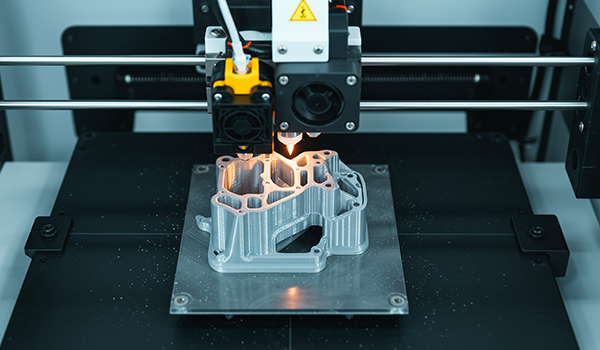
A conventional sand casting project often begins with a physical pattern and one or more core boxes. If the design changes, part of that tooling may need to be modified or rebuilt.
3D sand printing uses a digital model to build molds and cores layer by layer, commonly through binder jetting. It can remove the need for a conventional pattern in selected projects and make complicated core geometries easier to manufacture.
Patternless Mold Production
Patternless production means that the mold cavity is generated directly from digital manufacturing data. Design changes can be applied to the CAD model and reflected in a new mold without modifying permanent pattern equipment.
This is especially relevant during prototype development, low-volume production, replacement-part manufacturing, and projects in which blade or passage geometry may change after testing.
Complex Core Design
Printed cores can contain curved passages, branching geometries, integrated locating features, and shapes that are difficult to withdraw from a conventional core box.
For impellers, this capability can help reproduce enclosed flow passages. It can also reduce the need to divide a complicated core into multiple sections, although core strength and handling requirements remain important.
Digital Design Revisions
Digital molds make design iteration more flexible, but every revision must still be reviewed by a casting engineer. A CAD model that is printable may contain sections that fill poorly, cool unevenly, trap gas, or create difficult cleaning conditions.
The previous guide to 3D Printing for prototypes explains how concept models, fit samples, functional prototypes, and pre-production parts answer different engineering questions.
What Do Recent 2026 Studies Say About Printed Sand Molds?
Recent foundry research has moved beyond asking whether sand molds can be printed. Current work examines binder behavior, permeability, gas evolution, thermal control, gating design, and defect reduction.
A July 2026 study published in the Archives of Foundry Engineering evaluated resin content, curing conditions, and sand grading in 3D-printed furan sand molds. The findings demonstrate that increasing binder is not automatically beneficial because mold strength must be balanced against gas evolution and permeability.
Another 2026 paper in the International Journal of Metalcasting investigated lattice-structured printed sand molds as a method for reducing hot tearing and hot cracking. This reflects a broader shift toward designing the mold’s thermal behavior rather than treating it as a passive container.
Research on dynamic gating in 3D-printed sand molds, published in a 2026 issue of the same journal, also studied how additive manufacturing can change gating design and reduce post-casting work.
These developments are relevant to complex pump parts because impeller quality depends on controlled filling, feeding, cooling, and removal of the gating system. Nevertheless, research results must be adapted to the actual alloy, component geometry, molding system, printer, and foundry conditions.
Step-by-Step Impeller Casting Process
The complete impeller casting process begins before metal is melted. It starts with understanding the operating conditions and determining which features are critical to hydraulic and mechanical performance.
Step 1: Review the Application
The manufacturer should understand the type of pump or machine, operating speed, fluid, pressure, temperature, corrosion conditions, expected service life, and inspection requirements.
These details guide material selection and help distinguish critical dimensions from non-functional surfaces.
Step 2: Check the CAD Model and Drawing
The three-dimensional model defines blade geometry, flow passages, hub shape, and overall form. The two-dimensional drawing identifies tolerances, datums, surface finish, material grade, heat treatment, and testing requirements.
Both documents are useful. A CAD model alone may not communicate the intended tolerance system or inspection priorities.
Useful File Information
The request should include STEP, IGES, Parasolid, or another compatible 3D file, together with a controlled drawing revision. The manufacturer should also receive the required quantity, target production method, and expected annual demand.
Step 3: Select the Alloy
The alloy must provide the required combination of corrosion resistance, strength, castability, weldability, machinability, and wear resistance.
Common choices may include cast iron, carbon steel, stainless steel, duplex stainless steel, nickel alloys, aluminum alloys, or cobalt-based materials. The correct selection depends on the fluid and operating environment rather than the general product name.
Step 4: Select the Casting Route
A smaller precision impeller may suit silica sol investment casting, while a larger component may require resin sand casting. A prototype or complicated replacement part may benefit from a 3D-printed sand mold.
The decision should compare total manufacturing requirements, including pattern work, mold preparation, machining, finishing, inspection, and repeatability.
Step 5: Design the Mold and Core
The mold design establishes parting lines, core locations, draft where required, machining allowances, and methods for securing the internal geometry.
Core prints and locating features must hold the core in the correct position. Core movement can change passage thickness and produce hydraulic imbalance.
Step 6: Engineer Gating and Feeding
The gating system controls how metal enters the cavity. The feeding system supplies additional liquid metal as the casting solidifies and contracts.
For a complex casting impeller, the system should fill thin blades without creating damaging turbulence, oxide entrainment, premature freezing, or isolated hot spots.
Riser
A riser is a reservoir of molten metal connected to the casting. It feeds sections that shrink during solidification.
The riser must remain liquid long enough to supply the casting. Its position and size should be determined according to the thermal behavior of the component.
Runner
The runner distributes molten metal from the sprue to the gates. Its design influences flow velocity and how evenly different sections begin filling.
A poorly designed runner can contribute to uneven filling, inclusions, or cold shuts in blade sections.
Step 7: Produce the Mold
For investment casting, this stage includes pattern assembly, shell building, drying, dewaxing, and firing. For resin sand casting, it includes sand preparation, molding, core production, coating where required, and assembly.
When a printed sand mold is used, printer calibration, layer consistency, binder content, curing, cleaning, and dimensional verification become important controls.
Step 8: Melt and Pour the Alloy
The selected metal is melted and its chemistry is controlled according to the specified grade. Pouring temperature and time must suit the alloy, mold, and impeller geometry.
Clean metal handling helps reduce inclusions and oxidation. The exact procedure should follow the foundry’s qualified process and applicable material standards.
Step 9: Solidification and Shakeout
After pouring, the casting cools inside the mold. The cooling sequence affects grain structure, shrinkage, residual stress, and distortion.
The part is removed after sufficient solidification. Premature removal may cause deformation, while unnecessary delay can reduce production efficiency.
Step 10: Remove Gates and Clean the Casting
Gates, risers, adhered sand, ceramic shell, and excess metal are removed. Blasting, grinding, and local finishing prepare the component for inspection and machining.
Removal should not damage blade edges or reduce required wall thickness. Any repair procedure should be controlled and documented when specified.
Step 11: Heat Treatment
Heat treatment may be required to achieve mechanical properties, relieve stress, improve corrosion performance, or stabilize the microstructure.
The selected cycle depends on the alloy specification and casting condition. Heat treatment should not be copied from a different alloy with a similar commercial name.
Step 12: CNC Machine Critical Features
The bore, keyway, shaft interface, seal areas, mounting faces, and datum surfaces usually require accurate machining. CNC machining also establishes concentricity between the functional features.
Machining should reference stable datums rather than irregular as-cast surfaces. Sufficient casting allowance must remain after cleaning and heat treatment.
Step 13: Inspect and Balance the Impeller
The final casting may require chemical analysis, mechanical testing, dimensional inspection, surface examination, penetrant testing, magnetic-particle testing, radiography, ultrasonic inspection, or pressure-related evaluation.
Static or dynamic balancing is then performed according to component speed, size, and applicable specification.
Investment Casting vs 3D-Printed Sand Casting
These methods are not direct substitutes in every application. Each solves a different combination of size, complexity, finish, tooling, and production-volume requirements.
| Selection factor | Fundición de precisión | 3D-printed sand casting |
|---|---|---|
| Pattern requirement | Uses a sacrificial pattern | Can produce molds directly from digital data |
| Surface condition | Generally smoother | Generally rougher |
| Fine external detail | Strong capability | Depends on sand and printing resolution |
| Large component suitability | More limited | Better suited to many large castings |
| Design revisions | Requires a new or modified pattern | CAD data and mold can be revised |
| Internal core complexity | Possible but process-dependent | Strong capability for complex sand cores |
| Post-casting machining | Required on critical interfaces | Often more extensive |
| Typical role | Precision production and detailed impellers | Prototypes, large parts, complex cores and flexible quantities |
Choose Investment Casting When
Investment casting is suitable when the impeller requires detailed blades, a smoother as-cast surface, relatively controlled dimensions, and repeat production.
The pattern and shell route becomes more practical after the geometry has been validated and the anticipated quantity supports the required preparation.
Choose 3D-Printed Sand Casting When
Printed sand molds are attractive when the part is large, internally complex, required in limited quantities, or likely to undergo design revisions.
They can also support legacy replacement parts when usable CAD data can be reconstructed. Dimensional verification is especially important when the model originates from scanning an existing worn component.
How Material Selection Changes Impeller Performance
Material selection should begin with the fluid and operating environment. The same geometry may require different alloys in clean water, seawater, chemical processing, slurry transport, or high-temperature service.
Hierro fundido
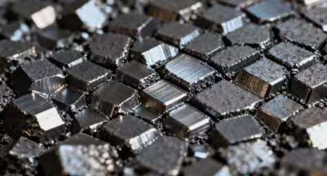
Cast iron offers good castability, vibration-damping behavior, and practical wear performance for many general pump applications.
Its suitability depends on fluid chemistry, impact conditions, pressure, and corrosion risk. It should not be selected solely because the original pump housing used iron.
Acero inoxidable
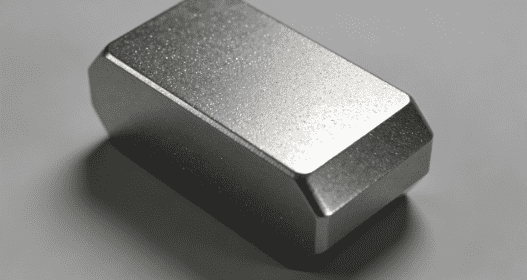
Stainless steel is widely used when corrosion resistance, cleanliness, and mechanical performance are important. Grades such as 304 or 316 serve different environments, while duplex grades may be considered for higher strength and resistance to localized corrosion.
The casting specification, heat treatment, chemistry, and inspection requirements must be clearly defined. “Stainless steel” alone is not a complete material designation.
Acero inoxidable dúplex
Duplex stainless steel combines ferritic and austenitic microstructures. It can offer high strength and strong resistance to certain forms of corrosion.
However, its performance depends on composition, heat treatment, phase balance, and manufacturing control. It requires a more disciplined impeller casting process than a generic material substitution.
Nickel and Cobalt Alloys
Nickel-based alloys may be considered for aggressive chemicals or demanding temperature conditions. Cobalt-based materials may be used where hot wear, erosion, or severe surface conditions are involved.
These materials require careful melting, casting, heat treatment, and machining planning. Their use should be based on actual service requirements.
Common Impeller Casting Defects and Their Causes
A visible defect is not always the only concern. Internal discontinuities, distortion, chemistry variation, and mass imbalance can also affect operation.
| Defecto | Possible cause | Potential effect | Control focus |
|---|---|---|---|
| Incomplete blade filling | Low fluidity, early freezing or poor gating | Distorted hydraulic passage | Filling analysis and pouring control |
| Porosidad del gas | Mold gas, moisture or turbulent filling | Reduced integrity and leakage risk | Binder, venting and metal handling |
| Shrinkage cavity | Insufficient feeding or isolated hot spot | Loss of strength | Riser and solidification design |
| Sand inclusion | Mold erosion or poor cleaning | Rough passage and local weakness | Mold strength and flow control |
| Blade distortion | Uneven cooling or residual stress | Hydraulic imbalance | Section design and heat control |
| Surface crack | Stress concentration or unsuitable handling | Reduced durability | Geometry, cooling and inspection |
| Dimensional mismatch | Core movement or mold variation | Assembly and flow problems | Core location and dimensional checks |
| Excess imbalance | Uneven mass or machining error | Vibration and bearing load | Controlled machining and balancing |
Porosidad
Porosity consists of small voids caused by gas or solidification behavior. Its effect depends on size, location, distribution, and the stresses applied to the component.
A defect near a highly stressed hub or thin blade may be more significant than one in a low-stress area. Acceptance should follow the drawing and applicable specification.
Contracción
Shrinkage occurs because metal contracts as it cools and solidifies. Heavy hub sections are particularly important because they can remain hot after thin blades begin freezing.
Feeding design, local cooling control, and section transitions help manage this risk.
Core Shift
Core shift changes the position of an internal passage. It can create uneven blade or shroud thickness even when the external casting appears correct.
Secure locating features, mold assembly control, and dimensional inspection are necessary for closed impellers.
Quality Control for a Pump Impeller Casting
Quality control should focus on features that influence hydraulic performance, structural integrity, assembly, and rotational behavior.
Material Verification
Chemical composition confirms whether the casting corresponds to the specified alloy. Mechanical tests may verify tensile strength, yield behavior, elongation, hardness, or impact performance where required.
Material certificates should remain traceable to the melt, heat-treatment batch, and component identification.
Inspección dimensional
Coordinate measuring machines, gauges, scanning, and conventional instruments can be used according to the geometry and tolerance.
Blade profiles, passage widths, bore dimensions, hub locations, and reference surfaces deserve particular attention.
Ensayos no destructivos
Liquid penetrant testing can reveal selected surface-breaking defects in nonporous materials. Magnetic-particle testing may be used for suitable ferromagnetic alloys.
Radiographic or ultrasonic testing may be specified for internal quality, depending on geometry, alloy, thickness, and acceptance criteria.
Static and Dynamic Balancing
Static balancing identifies whether the center of mass is offset from the rotational axis. Dynamic balancing evaluates imbalance across more than one plane while the part rotates.
The required method depends on operating speed, impeller width, mass, system sensitivity, and the relevant balancing requirement.
How to Prepare an RFQ for Impeller Casting
A clear RFQ allows the foundry to evaluate casting feasibility, machining, inspection, and production risk together.
Include:
- 3D CAD model and controlled 2D drawing
- Impeller type, diameter, width, and approximate weight
- Alloy grade and applicable material standard
- Annual quantity and initial sample quantity
- Operating speed and direction of rotation
- Fluid type, temperature, pressure, and corrosion conditions
- Critical blade, bore, keyway, and interface dimensions
- Surface finish requirements
- Heat-treatment requirements
- Machining scope and machining allowances
- Non-destructive testing and acceptance standards
- Static or dynamic balancing requirements
- Material certificate and inspection-document requirements
- Prototype and production delivery expectations
Leierwo’s pump manufacturing capabilities cover pump bodies, impellers, sleeves, guide components, casting, and precision machining. Its product range also includes double suction impellers for high-flow industrial pump systems and compressor impellers for gas-handling equipment.
PREGUNTAS FRECUENTES
What is the best casting process for a pump impeller?
The best process depends on diameter, blade complexity, alloy, quantity, surface condition, and tolerance. Investment casting often suits smaller detailed impellers, while resin sand casting is practical for larger parts. Printed sand molds can support prototypes, complex cores, and frequently revised designs.
Can 3D-printed sand molds produce functional metal impellers?
Yes. The printer produces the sand mold or core rather than the finished metal component. Molten alloy is still poured and solidified through a foundry process. Mold strength, binder behavior, gas generation, permeability, gating, feeding, heat treatment, machining, inspection, and balancing remain essential.
Why does a cast impeller need CNC machining?
Casting creates the main geometry, but the bore, shaft connection, keyway, sealing face, and reference surfaces often require tighter tolerances. CNC machining establishes accurate dimensions and concentricity. It also prepares functional interfaces before final dimensional inspection and balancing.
How can manufacturers reduce porosity in impeller castings?
Porosity control begins with the alloy, melt cleanliness, mold condition, binder level, venting, gating design, pouring practice, and solidification plan. Because gas porosity and shrinkage porosity have different causes, the defect should be identified before changing the process or adding unnecessary metal.
What files are needed to quote an impeller casting project?
A useful quotation package includes a STEP or compatible 3D model, a controlled 2D drawing, alloy grade, quantity, operating conditions, critical tolerances, machining scope, surface requirements, inspection standards, balancing grade, and delivery target. Complete information reduces assumptions during process planning.
Conclusión
The impeller casting process is more than pouring metal into a mold. It combines hydraulic geometry, material engineering, mold and core design, filling control, solidification, heat treatment, CNC machining, inspection, and balancing.
Investment casting remains valuable for detailed precision impellers, while resin sand casting supports larger and heavier components. The rapid development of 3D-printed sand molds adds a flexible option for prototypes, complex cores, replacement parts, and designs that may change before stable production.
Recent 2026 research shows that printed molds are also becoming engineered thermal and flow-control tools. Binder dosage, sand grading, permeability, gas generation, lattice geometry, and dynamic gating can all influence the casting result. These developments create new opportunities, but they do not remove the need for experienced foundry planning.
By connecting 3D Printing services with investment casting, resin sand casting, CNC machining, testing, and pump-component production, Leierwo can evaluate a project from the first digital model through prototype validation and finished impeller inspection.
Categorías de productos
- Piezas de válvulas
- Piezas de la bomba de agua
- Piezas de la caja de cojinetes
- Piezas de fundición a presión
- Productos para bombas de acero inoxidable
- Productos para bombas de hierro fundido
- Piezas de válvulas para automóviles
- Recambios para automóviles
- Piezas de válvulas para uso civil
- Piezas de bomba de vacío KF

¡Comencemos tu próximo proyecto!
Inicie su proyecto con Leierwo
1. Envíe su consulta
2. Cálculo de costes
3. Inicio de la producción
4. Organizar la entrega
PREGUNTAS FRECUENTES
Sí, tenemos una amplia experiencia en el comercio internacional y podemos ayudar a los clientes con el despacho de aduanas de exportación y los arreglos de envío. Aceptamos varios métodos de pago internacionales, incluyendo T/T (transferencia telegráfica), transferencia bancaria y carta de crédito (L/C). Las condiciones de pago se pueden discutir con nuestro equipo de ventas.
Al asociarse con Leierwo, podrá disfrutar de precios competitivos y una calidad superior a la de otros proveedores. Además, ofrecemos una solución integral para entregar piezas acabadas, incluido el mecanizado CNC y el tratamiento de superficies, lo que garantiza un proceso de producción sin fisuras.
Contamos con avanzados equipos de fundición y estrictos sistemas de control de calidad. Nuestra capacidad de producción mensual es considerable y podemos fabricar productos a partir de dibujos o muestras proporcionados por el cliente. Aceptamos tanto pequeños pedidos de prueba como producciones a gran escala.
Nuestros productos cumplen normas internacionales como ASTM, AISI, DIN y JIS. Podemos proporcionar informes de pruebas de materiales y certificaciones pertinentes para garantizar que la calidad del producto cumple los requisitos del cliente.
Seguimos estrictamente el sistema de gestión de calidad ISO 9001 y realizamos múltiples inspecciones a lo largo del proceso de producción, incluidos análisis espectrográficos, pruebas de rayos X, pruebas ultrasónicas y mediciones dimensionales. Estas medidas de control de calidad garantizan que nuestras piezas de fundición cumplen las normas más estrictas.
Sin embargo, somos flexibles y estamos abiertos a discutir sus necesidades específicas.
Nuestro plazo de producción estándar es de 4 a 6 semanas, en función de la cantidad del pedido y la complejidad del producto. Nos esforzamos por acortar los plazos de entrega para satisfacer las demandas de los clientes.
Sí, podemos proporcionar muestras para la inspección de calidad. Los costes de las muestras y los gastos de envío pueden negociarse, y los gastos de las muestras pueden reembolsarse al realizar un pedido formal.
 Spanish
  English
  Arabic
  Malay
Malay  German