
3D Printing for Prototypes: From Design Validation to Production
يسعدني وجودك هنا! قبل أن نتعمق في المحتوى، أود أن تنضموا إليّ على منصات التواصل الاجتماعي. هناك أشارككم أفكارًا إضافية، وأتواصل مع مجتمعنا الرائع، وأُطلعكم على آخر الأخبار. إليكم كيفية البقاء على تواصل:
📘 فيسبوك: شركة شنغهاي لييروو الصناعية التجارية المحدودة
الآن، لننطلق في هذه الرحلة معًا! آمل أن تجدوا هذا المحتوى مفيدًا ومُلهمًا وقيّمًا. هيا بنا!
جدول المحتويات
أهم النقاط
- 3D Printing converts CAD models into physical prototypes without requiring conventional molds or dedicated tooling.
- Different prototypes serve different purposes, including appearance review, assembly testing, functional validation, and pre-production approval.
- FDM is economical for early concepts, SLA offers detailed surfaces, SLS produces durable polymer parts, and metal printing supports demanding functional tests.
- A successful prototype must be designed around its intended test rather than simply printed at the lowest possible price.
- Printed patterns and sand molds can connect digital prototyping with investment casting and sand casting.
- CNC machining may be more suitable when exact production materials, tight tolerances, or machined surface conditions must be evaluated.
- The best product development plan often combines additive manufacturing, casting, machining, inspection, and controlled design revisions.
- Buyers should provide complete CAD files, material requirements, quantities, tolerances, finishes, and testing objectives when requesting a quotation.
ما هو 3D Printing for Prototypes?
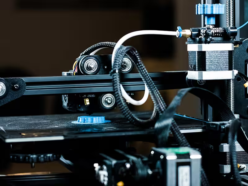
3D Printing for prototypes is the process of turning a three-dimensional digital design into a physical model by adding material layer by layer. It allows engineers to examine a component before committing to molds, tooling, casting production, or large-volume manufacturing.
The term is closely connected with rapid prototyping, which describes techniques used to quickly produce physical models from CAD data. According to the National Institute of Standards and Technology, additive manufacturing builds three-dimensional products from digital designs, usually through a layer-by-layer process.
Unlike a drawing or computer rendering, a physical prototype can be held, assembled, measured, presented to customers, and tested under controlled conditions. This makes 3D Printing valuable during both early product development and final engineering verification.
Prototype Versus Production Part
A prototype is primarily manufactured to answer questions. It may confirm appearance, size, assembly, movement, ergonomics, material behavior, or manufacturability.
A production part must consistently satisfy final specifications under actual operating conditions. Some printed components can become end-use parts, but a prototype should not automatically be treated as production-ready without appropriate material validation and testing.
التصنيع الإضافي
Additive manufacturing is the broader technical term for processes that build objects through successive addition of material. The terminology is formally defined in ISO/ASTM 52900.
In industrial projects, additive manufacturing may cover prototypes, tools, casting patterns, molds, fixtures, replacement parts, and finished components. The appropriate application depends on material performance, dimensional requirements, order quantity, and cost.
Rapid Iteration
Rapid iteration means manufacturing, testing, revising, and reproducing a design in short cycles. Because conventional tooling is usually unnecessary, an engineer can modify the CAD model instead of rebuilding an expensive mold.
This approach helps reveal problems while changes remain relatively inexpensive. It is particularly useful for new products, customized equipment, complex industrial parts, and components with uncertain geometry.
Why Use 3D Printing During Product Development?
The greatest benefit of 3D Printing is not simply faster part production. Its real value is the ability to identify design risks before they become expensive production problems.
A digital model may appear complete while still containing inaccessible fasteners, insufficient clearances, uncomfortable grips, thin walls, weak joints, or difficult manufacturing features. A physical prototype makes these issues easier to recognize.
Faster Design Validation
Traditional prototype manufacturing may require patterns, molds, fixtures, and several machining setups. These preparations can be difficult to justify when the design is still changing.
3D Printing can manufacture individual versions directly from revised digital files. Design teams can compare multiple concepts and select a stronger option before investing in production tooling.
Lower Tooling Risk
Tooling changes can be costly, especially when a defect is discovered after mold production. Printed prototypes allow teams to verify important dimensions, wall thicknesses, interfaces, and assembly relationships earlier.
This does not eliminate the need for engineering review. Instead, it gives engineers physical evidence that can support more reliable decisions.
Better Communication
A printed model helps customers, engineers, operators, and purchasing teams discuss the same physical object. This reduces misunderstandings that may occur when stakeholders interpret technical drawings differently.
Models are also useful for sales demonstrations, exhibitions, internal approval meetings, and design presentations. A realistic prototype can explain size and function more effectively than a two-dimensional image.
Complex Geometry
Additive processes can create curved channels, hollow structures, internal passages, organic shapes, and lightweight geometries that are difficult to machine conventionally. This gives engineers more freedom when exploring new solutions.
However, printable does not always mean manufacturable through the intended production process. A design planned for casting, machining, or forging must still follow the rules of its final method.
Types of Prototypes Made with 3D Printing
A buyer should first define what the prototype needs to prove. Selecting a process without a clear testing purpose can result in unnecessary expense or misleading results.
Concept Models
Concept models communicate the basic shape, dimensions, and visual proportions of a product. They are normally produced quickly and do not need to reproduce final mechanical properties.
أفضل استخدام
These models are suitable for early design reviews, customer presentations, packaging studies, and comparison of several design directions. FDM and basic resin printing are common choices.
Appearance Prototypes
Appearance prototypes focus on surface quality, color, texture, geometry, and visual detail. They may be sanded, polished, painted, plated, or otherwise finished to resemble a final product.
أفضل استخدام
They are useful for consumer products, housings, display components, control panels, and parts requiring management or customer approval. SLA is frequently selected because it can reproduce fine details and smooth surfaces.
Form-and-Fit Prototypes
Form-and-fit models verify whether components have the correct size and can be assembled as intended. Engineers use them to inspect clearances, mounting points, holes, interfaces, access space, and interference between parts.
أفضل استخدام
This prototype is valuable for machinery, pump and valve assemblies, electronic housings, automotive components, brackets, and industrial equipment. Dimensional accuracy should be selected according to the assembly’s functional requirements.
Functional Prototypes
Functional prototypes are used to evaluate movement, loading, fluid flow, impact, heat exposure, sealing, or other operating conditions. Their material and manufacturing process must be sufficiently representative of the intended test.
أفضل استخدام
SLS, engineering-grade polymers, metal printing, casting, or CNC machining may be required. A decorative resin model should not be used to predict the strength of a production metal component.
Pre-Production Prototypes
A pre-production prototype is manufactured when the design is close to final approval. It may combine the intended material with casting, machining, heat treatment, surface finishing, and inspection.
أفضل استخدام
These samples help confirm the manufacturing route before serial production. Leierwo’s integrated manufacturing services can support the transition from a digital prototype to casting, machining, finishing, and production verification.
Which 3D Printing Technology Is Best for Prototypes?
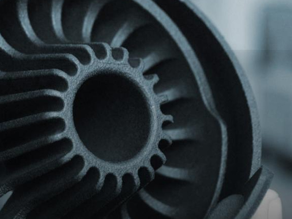
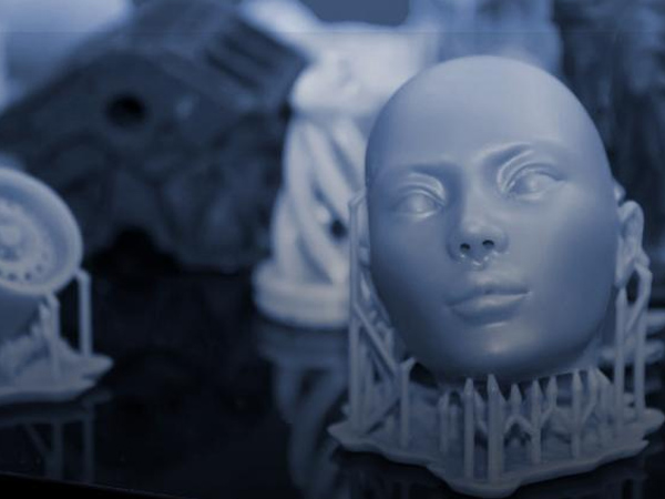
No single technology is best for every project. Buyers should compare resolution, material performance, surface finish, part size, speed, and budget.
| التكنولوجيا | Main Materials | Key Advantage | Main Limitation | Suitable Prototype |
|---|---|---|---|---|
| FDM/FFF | PLA, ABS, PETG, nylon | Affordable and fast | Visible layers and direction-dependent strength | Concept and basic fit models |
| جيش تحرير السودان | Photopolymer resin | Fine detail and smooth finish | Some resins can be brittle | Appearance and detailed models |
| SLS | Nylon and polymer powders | Durable parts without conventional supports | Grainier surface and higher cost | Functional and assembly testing |
| Metal powder-bed printing | Stainless steel, aluminum, titanium and other alloys | Complex functional metal geometry | Expensive with more post-processing | Metal performance prototypes |
| Binder jetting | Polymer, metal, or sand systems | Efficient production of complex forms | Strength and finish depend on material and processing | Patterns, molds, and selected parts |
| Material jetting | Photopolymers | High visual detail and multi-material capability | Material performance may differ from final production parts | Presentation and ergonomic models |
For a more detailed process comparison, readers can review Leierwo’s guide to choosing the right 3D Printing technology.
FDM for Fast Concept Testing
FDM deposits melted thermoplastic through a nozzle. It is generally a practical option when speed, size, and low cost matter more than a flawless surface.
The process can produce fixtures, housings, brackets, and assembly models. Print orientation and layer bonding should be considered when the component will be mechanically tested.
SLA for Detailed Visual Models
Stereolithography cures liquid photopolymer with controlled light. It can reproduce small features and smoother surfaces than many filament-based systems.
SLA is appropriate for presentation models, master patterns, housings, and parts with detailed external geometry. Resin selection remains important because standard photopolymers may not reproduce the toughness or temperature resistance of production plastics.
SLS for Functional Polymer Parts
SLS uses energy to fuse polymer powder. Because surrounding powder supports the component during printing, it can produce interlocking parts and complicated geometries without conventional support structures.
Nylon SLS components are often suitable for snap fits, hinges, enclosures, ducts, and moderate mechanical evaluation. Surface texture and dimensional requirements should still be reviewed before ordering.
Metal 3D Printing for Performance Testing
Metal printing can manufacture complex stainless steel, aluminum, titanium, and specialty alloy components. It is useful when the prototype must be evaluated in metal or when internal geometry cannot be created through ordinary machining.
The printed part may require heat treatment, support removal, surface finishing, machining, and dimensional inspection. Buyers comparing stainless steel additive manufacturing with subtractive production can read 3D Print 316 Stainless vs Traditional Machining.
3D Printing Prototype Workflow
A controlled workflow is more important than printing the design immediately. Each stage should connect the prototype with a specific engineering question.
Step 1: Define the Test Objective
Decide whether the model must demonstrate appearance, assembly, ergonomics, motion, strength, temperature resistance, or manufacturability. One inexpensive model may be enough for visual review, while several material-specific samples may be required for functional validation.
A clear objective prevents buyers from paying for performance they do not need. It also prevents an unsuitable model from being used for a safety-critical decision.
Step 2: Prepare the CAD Model
The three-dimensional model should contain the correct dimensions, wall thicknesses, holes, fillets, interfaces, and internal geometry. Common quotation formats include STEP, IGES, Parasolid, and native CAD files.
The model should also be checked for open surfaces, overlapping bodies, inverted faces, and features below the selected process limit. A drawing can supplement the CAD file by identifying tolerances, material grades, surface requirements, and inspection points.
Step 3: Select the Process and Material
Process selection should be based on the test objective rather than familiarity with a particular machine. For example, a resin model may be ideal for a visual review but unsuitable for impact testing.
Material choice should consider stiffness, elongation, heat resistance, corrosion conditions, weight, transparency, surface quality, and similarity to the intended production material.
Step 4: Review Print Orientation
Orientation influences visible layers, support marks, dimensional behavior, build time, and mechanical performance. A component printed vertically may behave differently from the same component printed horizontally.
Important cosmetic surfaces and load directions should be identified before production. When possible, critical dimensions should be oriented and finished to support reliable measurement.
Step 5: Manufacture and Post-Process
After slicing, the prototype is built layer by layer. Post-processing may include support removal, cleaning, curing, blasting, sanding, polishing, painting, heat treatment, or machining.
Post-processing requirements should be included in the quotation because they can affect lead time and price. A raw prototype and a presentation-grade model may have significantly different total costs.
Step 6: Inspect and Test
Dimensional inspection should focus on features that affect assembly or performance. Functional testing should reflect the conditions defined at the beginning of the project.
Results should be recorded so that every design change has a clear reason. This creates a traceable development process rather than a series of undocumented print revisions.
Step 7: Revise the Design
After testing, the CAD model may require changes to wall thickness, ribs, joints, channels, clearances, or mounting features. The updated design can then be printed again for confirmation.
Once the geometry is stable, engineers can evaluate whether 3D Printing, casting, CNC machining, or another process is best for production.
3D Printing vs CNC Machining for Prototypes
Both methods can produce valuable prototypes, but they answer different engineering needs.
| Decision Factor | الطباعة ثلاثية الأبعاد | تصنيع الآلات باستخدام الحاسب الآلي |
|---|---|---|
| Initial setup | Usually low without dedicated tooling | Requires programming, setup, and workholding |
| Complex internal geometry | Strong advantage | Limited by tool access |
| Material similarity | Depends on available printable materials | Can use many production-grade materials |
| التحمل الضيق | Depends on process and post-machining | Generally better for precision features |
| Design revisions | Easy to update digital files | New setup or programming may be required |
| Surface finish | Often requires finishing | Machined surfaces can be produced directly |
| Material waste | Builds near-net shapes | Removes material from stock |
| Best application | Fast iteration and complex geometry | Precise, material-representative testing |
Choose 3D Printing when design iteration, geometric freedom, and tooling avoidance are the priorities. Choose CNC machining when the prototype must closely reproduce production material, machined tolerances, sealing faces, threads, or bearing interfaces.
A hybrid approach is often stronger. The main geometry can be printed, while critical holes, sealing surfaces, and datums are machined afterward.
3D Printing vs Casting for Prototype Metal Parts
Casting becomes important when a prototype must represent the properties and manufacturing characteristics of a cast component. Printed patterns, molds, and cores can accelerate this transition.
Direct Printed Prototype
A direct printed part is created from polymer or metal without first making a conventional mold. It is ideal for quick geometry changes and very small quantities.
The limitations depend on the selected technology. Material properties, surface condition, and dimensional behavior may differ from those of a final casting.
Printed Pattern for Investment Casting
A printed sacrificial pattern can replace or supplement conventionally tooled wax patterns for selected development projects. The pattern is incorporated into an investment casting workflow and removed before molten metal is poured.
This method can be useful for complex metal prototypes and low-volume components when hard tooling is not yet justified. Buyers planning precision metal parts can consult the Precision Investment Casting Guide.
Printed Sand Mold or Core
Binder-based systems can create sand molds and cores directly from digital data. They are particularly useful for complex passages, large castings, and designs that would require difficult pattern equipment.
The casting still requires appropriate gating, feeding, alloy control, pouring, cleaning, inspection, and possibly machining. Learn more about conventional options in the Sand Casting Products Guide.
How to Design Better 3D-Printed Prototypes
Good results begin with a design that reflects both the printing process and the prototype’s purpose.
Use Realistic Wall Thicknesses
Extremely thin walls can deform, break, or fail to print consistently. Wall thickness should match the process, material, part size, and expected load.
If the component will eventually be cast, the design should also consider suitable casting wall transitions. A printable feature may still create filling, cooling, or shrinkage problems during casting.
Add Functional Clearances
CAD assemblies may fit perfectly on screen while physical components bind after manufacturing. Sliding fits, snap fits, shafts, fasteners, and moving joints require intentional clearance.
Test coupons can help determine a suitable gap before printing a large assembly. This is especially useful when the selected process has uncertain shrinkage or dimensional variation.
Reinforce High-Stress Features
Sharp internal corners, thin joints, and abrupt section changes can concentrate stress. Fillets, ribs, gradual transitions, and improved load paths may strengthen the design without adding excessive material.
The correct feature depends on how the prototype will be loaded. A part designed only for display does not need the same reinforcement as a working fixture.
Separate Large Assemblies Strategically
A large prototype may be divided into smaller printable sections. Joints should be positioned where they can be assembled, finished, and inspected without affecting key surfaces.
Pins, tabs, dovetails, screws, or adhesive joints can help align sections. The assembly plan should be decided before printing rather than improvised afterward.
Plan for Post-Processing
Support removal, sanding, drilling, tapping, painting, and machining require access and sufficient material. Critical surfaces may need a machining allowance.
If appearance matters, identify the visible surfaces before production. The printing orientation can then reduce support marks in important areas.
How Much Does a 3D-Printed Prototype Cost?
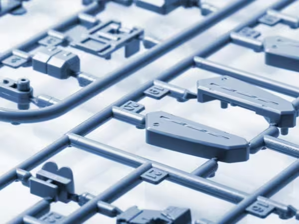
There is no universal price because prototype cost depends on geometry, dimensions, material, technology, finishing, tolerance, quantity, and testing requirements.
A small concept model may be inexpensive, while a large metal part with heat treatment, precision machining, and inspection can require a substantial budget.
Main Cost Factors
Part Volume and Build Height
More material and longer build time generally increase cost. Build height can influence machine time because the printer must complete more layers.
Geometry and Support Structures
Complex geometry is one of the strengths of 3D Printing, but extensive support structures can consume material and require additional removal work.
اختيار المواد
Standard polymers generally cost less than engineering-grade resins, high-performance thermoplastics, or metal powders. Material selection should therefore follow the actual test requirements.
تشطيب السطح
A raw print costs less than a polished, painted, plated, or machined model. Buyers should define which surfaces require cosmetic finishing and which can remain in the as-printed condition.
Inspection Requirements
Basic dimensional checks differ from a complete inspection report, scanning, pressure testing, material verification, or non-destructive examination. These requirements should be stated in the RFQ.
What Should Buyers Include in a Prototype RFQ?
A complete RFQ allows the manufacturer to select a more suitable process and provide a more accurate quotation.
Include the following information:
- A three-dimensional CAD file, preferably in STEP or another compatible solid-model format
- A two-dimensional drawing showing critical dimensions and tolerances
- Prototype purpose, such as display, assembly, flow, impact, or load testing
- Preferred material or required mechanical properties
- Overall dimensions and required quantity
- Surface finish, color, coating, or heat-treatment requirements
- Critical cosmetic and functional surfaces
- Inspection and reporting requirements
- Target delivery date
- Expected production method and future order volume
- Confidentiality or documentation requirements
Leierwo provides 3D Printing services alongside investment casting, sand casting, CNC machining, and post-processing. Providing complete project information helps its engineering team evaluate the path from prototype verification to scalable production.
Common Prototype Mistakes to Avoid
Choosing the Cheapest Material
The least expensive material may be acceptable for a concept model but misleading for a functional test. A prototype failure caused by unsuitable material does not necessarily indicate a poor product design.
Select material according to the question being tested. Appearance, assembly, heat, impact, and load evaluation may require different models.
Expecting Production Tolerances Automatically
Every additive process has dimensional capabilities and limitations. Very tight holes, threads, bearing seats, and sealing faces may require machining.
Specify only the tolerances that affect function. Applying tight tolerances to every dimension increases cost without necessarily improving the prototype.
Ignoring Build Direction
Layer orientation can influence strength, surface quality, and dimensional results. A load applied across layer interfaces may produce different performance from a load applied along the printed structure.
Tell the supplier how the component will operate. This information can influence process selection and orientation.
Treating One Prototype as Final Proof
A single prototype may confirm shape but not long-term durability, casting behavior, manufacturing consistency, or production economics. Different development stages often require different samples.
Use each iteration to answer a defined question. Move to the next stage only after the previous risk has been evaluated.
From 3D Printing to Production
The transition to production should be considered before the first model is printed. Early manufacturing input can prevent teams from approving a shape that is difficult or expensive to produce at scale.
Low-Volume Production
3D Printing may remain economical for customized components, replacement parts, complex products, or frequently changing designs. The absence of hard tooling can support flexible order quantities.
Unit cost, finishing time, inspection, and machine capacity must still be evaluated. A process suitable for ten parts may not be competitive for ten thousand.
Casting Production
Investment casting and sand casting can provide a practical route for metal parts after prototype approval. The right process depends on alloy, size, surface finish, tolerance, complexity, and quantity.
Leierwo works with stainless steel, carbon steel, alloy steel, aluminum alloys, zinc alloys, nickel alloys, titanium alloys, ductile iron, and gray iron across different manufacturing services. Its guide to top casting materials for industrial manufacturing can help buyers compare candidate material families.
CNC-Finished Components
Cast or printed near-net shapes may require CNC machining for threads, sealing faces, bores, and precision interfaces. Combining processes can reduce material removal while preserving functional accuracy.
The drawing should clearly distinguish as-formed surfaces from machined surfaces. This helps the manufacturer plan allowances, datums, fixtures, and inspection procedures.
FAQ About 3D Printing for Prototypes
Can I use 3D Printing to make a working prototype?
Yes, but the technology and material must match the intended test. FDM or resin may be suitable for basic mechanisms, while demanding mechanical, thermal, or pressure tests may require SLS, metal printing, casting, or CNC machining.
What is the best 3D Printing method for a first prototype?
FDM is often suitable for a low-cost concept or basic fit check. SLA is a stronger choice when fine detail and appearance matter, while SLS is appropriate for more durable functional polymer prototypes.
How fast can a 3D-printed prototype be made?
Simple parts may be completed quickly, but actual lead time depends on file preparation, size, machine availability, material, post-processing, inspection, and shipping. A complex metal prototype usually requires more time than a basic polymer model.
Do I need a 3D CAD file to request a quote?
A three-dimensional CAD file is normally required for accurate manufacturing evaluation. A two-dimensional drawing should also be supplied when the part has critical tolerances, material specifications, threads, surface finishes, or inspection requirements.
Is 3D Printing cheaper than CNC machining for one prototype?
It can be, especially for complex geometry or early designs that may change. CNC machining may deliver better value when production-grade material, tight tolerances, or precisely machined surfaces are essential to the test.
Can a printed plastic prototype replace a metal prototype?
Only when the test concerns shape, fit, appearance, or limited movement. Plastic cannot reliably represent metal stiffness, temperature performance, wear resistance, fatigue life, or load capacity.
Can 3D Printing be used to prototype cast metal parts?
Yes. Engineers can print a direct model for design review, create a sacrificial pattern for investment casting, or produce a sand mold or core for casting. The best route depends on alloy, size, geometry, quantity, and required properties.
How many prototype versions should I make before production?
There is no fixed number. Many projects progress through a concept model, form-and-fit sample, functional prototype, and pre-production sample, but simple products may need fewer stages.
Why does my printed prototype not fit the CAD assembly?
Possible causes include process variation, shrinkage, warping, insufficient clearance, support marks, post-processing, or incorrect design assumptions. Critical fits should be designed with realistic manufacturing tolerances and physically tested.
What should I ask a 3D Printing supplier before ordering?
Ask about process selection, material properties, achievable tolerances, build orientation, post-processing, inspection, expected lead time, confidentiality, and the proposed route to production. A capable supplier should explain why a method is suitable for your application.
خاتمة
3D Printing for prototypes gives product teams a direct way to transform digital designs into physical evidence. It supports faster design reviews, assembly verification, functional testing, customer communication, and earlier identification of manufacturing risks.
The strongest results come from selecting the process around the purpose of the test. FDM may be sufficient for a concept, SLA can improve visual evaluation, SLS can support durable polymer testing, and metal printing can address complex functional applications. When production properties or tight tolerances are essential, casting and CNC machining may become part of the prototype plan.
Leierwo combines الطباعة ثلاثية الأبعاد with precision casting, sand casting, machining, and finishing services. This integrated route allows buyers to verify a design, refine critical features, select a suitable material, and prepare the component for low-volume or serial manufacturing.
فئات المنتجات
- أجزاء الصمامات
- أجزاء مضخة المياه
- أجزاء صندوق المحمل
- أجزاء الصب بالقالب
- منتجات مضخات الفولاذ المقاوم للصدأ
- منتجات مضخات الحديد الزهر
- قطع غيار الصمامات لاستخدام السيارات
- قطع غيار السيارات
- أجزاء الصمامات للاستخدام المدني
- قطع غيار مضخة التفريغ KF

لنبدأ مشروعك القادم!
ابدأ مشروعك مع Leierwo
1. أرسل استفسارك
2. حساب التكلفة
3. بدء الإنتاج
4. ترتيب التسليم
الأسئلة الشائعة
نعم، لدينا خبرة واسعة في التجارة الدولية ويمكننا مساعدة العملاء في التخليص الجمركي للتصدير وترتيبات الشحن. نحن نقدم شروطًا تجارية مختلفة مثل FOB و CIF و DDP لتلبية الاحتياجات اللوجستية المختلفة، ونقبل طرق الدفع الدولية المختلفة، بما في ذلك T/T (التحويل البرقي) والتحويل البرقي وخطاب الاعتماد (L/C). يمكن مناقشة شروط الدفع مع فريق المبيعات لدينا.
من خلال الشراكة مع Leierwo، يمكنك الاستمتاع بأسعار تنافسية وجودة فائقة مقارنةً بالموردين الآخرين. بالإضافة إلى ذلك، نقدم حلاً شاملاً لتسليم الأجزاء الجاهزة، بما في ذلك التصنيع باستخدام الحاسب الآلي والمعالجة السطحية، مما يضمن عملية إنتاج سلسة.
لدينا معدات صب متقدمة وأنظمة صارمة لمراقبة الجودة. قدرتنا الإنتاجية الشهرية كبيرة، ويمكننا تصنيع المنتجات بناءً على الرسومات أو العينات المقدمة من العملاء. نحن نقبل كلاً من الطلبات التجريبية الصغيرة والإنتاج على نطاق واسع.
تتوافق منتجاتنا مع المعايير الدولية مثل ASTM و AISI و DIN و JIS. ويمكننا تقديم تقارير اختبار المواد والشهادات ذات الصلة لضمان توافق جودة المنتج مع متطلبات العملاء.
نحن نتبع بدقة نظام إدارة الجودة ISO 9001 ونجري عمليات فحص متعددة في جميع مراحل عملية الإنتاج، بما في ذلك التحليل الطيفي، واختبار الأشعة السينية، والاختبار بالموجات فوق الصوتية، وقياسات الأبعاد. تضمن تدابير مراقبة الجودة هذه أن مصبوباتنا تلبي أعلى المعايير.
يعتمد موك لدينا على نوع المنتج ومدى تعقيده، ومع ذلك، نحن مرنون ومنفتحون لمناقشة احتياجاتك الخاصة.
تتراوح مهلة الإنتاج القياسية لدينا من 4 إلى 6 أسابيع، حسب كمية الطلب وتعقيد المنتج. نسعى جاهدين لتقصير أوقات التسليم لتلبية طلبات العملاء.
نعم، يمكننا تقديم عينات لفحص الجودة. يمكن التفاوض بشأن تكاليف العينات ورسوم الشحن، ويمكن استرداد رسوم العينات عند تقديم طلب رسمي.
 Arabic
  English
  Spanish
  Malay
Malay  German